
Robotic Assembly of Discrete Cellular Lattices (digital materials) - Center for Bits and Atoms
(2013 - 2016)
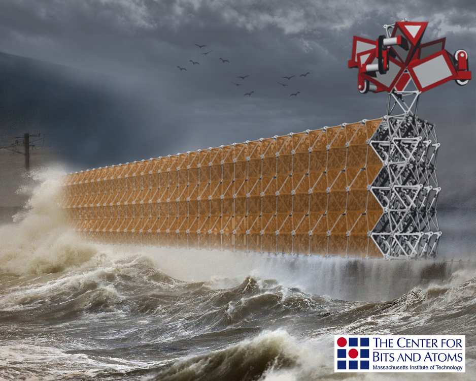
The designed and structured environment of digital cellular solids, exploited by mechatronically timed and optimized robotic assemblers, allows the creation of arbitrarily sized, functionally tuned, reconfigurable structures. These discretely assembled cellular lattices provide a structured environment for discrete motion systems. Specialized robotic machines make one bit motions relative to the structure, unbounded by traditional gantry-type motion systems. Assembler-bots, disassembler- bots, material-handler-bots, actuator-bots, all share common elements such as chassis, and power trains, yet, each type wield specialized manipulators for their tasks. A taxonomy of parts and machines has been and continues to evolve as each is an integral part of the robotic ecosystem of digital materials. Part type and assembler are mutually dependent, and, for real world applications, both are designed for manufacture. The scope of this research is the design of a discrete part-type and the associated assembler mechanisms of a digital cellular solid. The talk below gives an overview of the goals
Low-level assembly routines are the limiting factor to the digital assembly process. The overall efficiency of the digital fabrication assembly processes will be quantified by both assembly rate and the structural capabilities of the final systems. Optimization of path planning and material handling will likely affect overall system assembly rates, however the low-level one-bit motions that makeup the part placement and locomotion will be the primary limiting functions due to their high rate of occurrence. Quantification of the effectiveness of the assembly of digital materials is dependent upon the two most fundamental serial assembly procedures: parts placement and lattice locomotion.
More technical information is available in the following articles:
- US Patent 9,809,977
- Carney, Matthew, and Benjamin Jenett. "Relative Robots: Scaling Automated Assembly of Discrete Cellular Lattices." Proceedings of the 2016 Manufacturing Science, and Engineering Conference, June 2016. MSEC2016-8837
- Carney, Matthew (2015) "Discrete Cellular Lattice Assembly" (Masters Thesis).
The first interpretation of what a relative-assembler would look like is demonstrated below, and is followed by further evolutions of assembler concepts. The assembler moves relative to the structure being created.Discrete motions place discrete parts, and make discrete steps. The parts are stored flat-packed, and fed from a magazine. The assembler unpacks these elements into sparse-density, lattice structures. The regular, periodic lattice provides a highly structured environment. The kinematics of the robot are tuned to this periodicity, reducing placement uncertainty, allowing optimized part placement, and system locoomotion. This machine makes simple one-bit motions to retrieve a component, locate in the lattice and take a step to build the next adjoining cell.
Tolerances stackup is a concern in any assembly process. To simulate the effects of tolerances I built a javascript tool to help visualize what happens when multiple parts of varying dimension get stacked together. In the simulation, each component can vary in size. Each joint has a specified stiffness with which it can attach to its neighbor with. You can click and drag a component to watch how parts settle.
Controls are in a small window to the top right of your browser window. You can see the effect of various parameters. Note: This was a quick study and is not computational optimized and runs the risk of burdening your browser to the point of crashing your browser, requiring a refresh of the page or a browser restart (thanks for understanding browser optimization is not my specialty)!
The first prototype build of an assembler is shown below. This system is a gantry-based automation system, where motions are made along cartesian coordinates. Parts are picked up from a storage location, then placed onto a lattice. This machine has feet that attach to the structure, allowing attachment/detattchment, and relative motion.
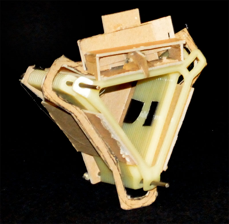
Koala Climber: mandrel based cell assembly and placement. In an effort to reduce uncertainty during part placement, a mandrel is used to tightly control the alignment of elements as they are formed into cells. In this way the placement of each element is done only with respect to the tolerance loop within the robot, rather than including the loop through the structure. This provides more certainty, and hence, speed capacity for placement.
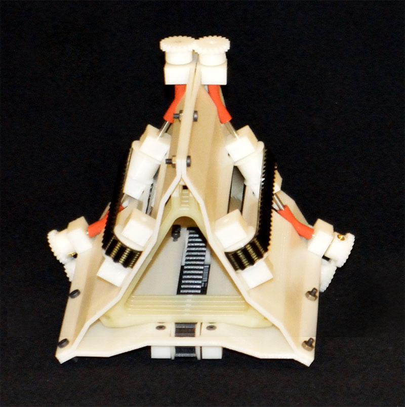
Leap Frog: mandrel assembly integrated into locomotion system. In this case, the locomotion system is also the mandrel based placement system. The feet of the robot kinematically align with respect to one another. Each placement of the foot is made with respect to the previous foot: each step is only dependent on the tolerance loop of the robot. One set of feet always remain attached to the structure. At each step cycle a cell of elements are placed. In this way, the locomotion system of the robot also acts as the tightly controlled mandrel-based placement system, reducing subsystem requirements, increasing certainty, and, hence, increasing assembly rates.
Dynamic Aperature Zipper: Rack and pinion locomotion system with chain connected elements. A zipper passively locates discrete elements in a periodic structure, the shape of the zipper mechanism being the equivalent of a mandrel that forces the arrangement of elements into specific kinematic orientations during placement. This face-connected octahedra lattice, however, has a periodically changing cross-sectional area, requiring a method of dynamically changing the aperature. A chain of discrete elements could be fed from a magazine into the structure with a rack and pinion type arrangement. That is the rollers both form the dynamic aperature and feed the parts into the column structure, which is the rack. The chain is neccessary to impose a distance constraint between structural elements.
The Flower Zipper: passive geometric assembly. Further study showed that by reversing the assembly direction of the octahedral column a passive geometry could, in fact, provide the kinematic trajectory to align, and fixture elements. A distance constraint between feeding elements fed through the geometry of the mandrel provides the position trajectory for fastening endpoints of the truss elements. In this way the part placement system is totally passive, and the tolerance loop of placement is independent of the locomotion system. It is a passive assembly system beyond the single degree of freedom required to travel the length of the colument.
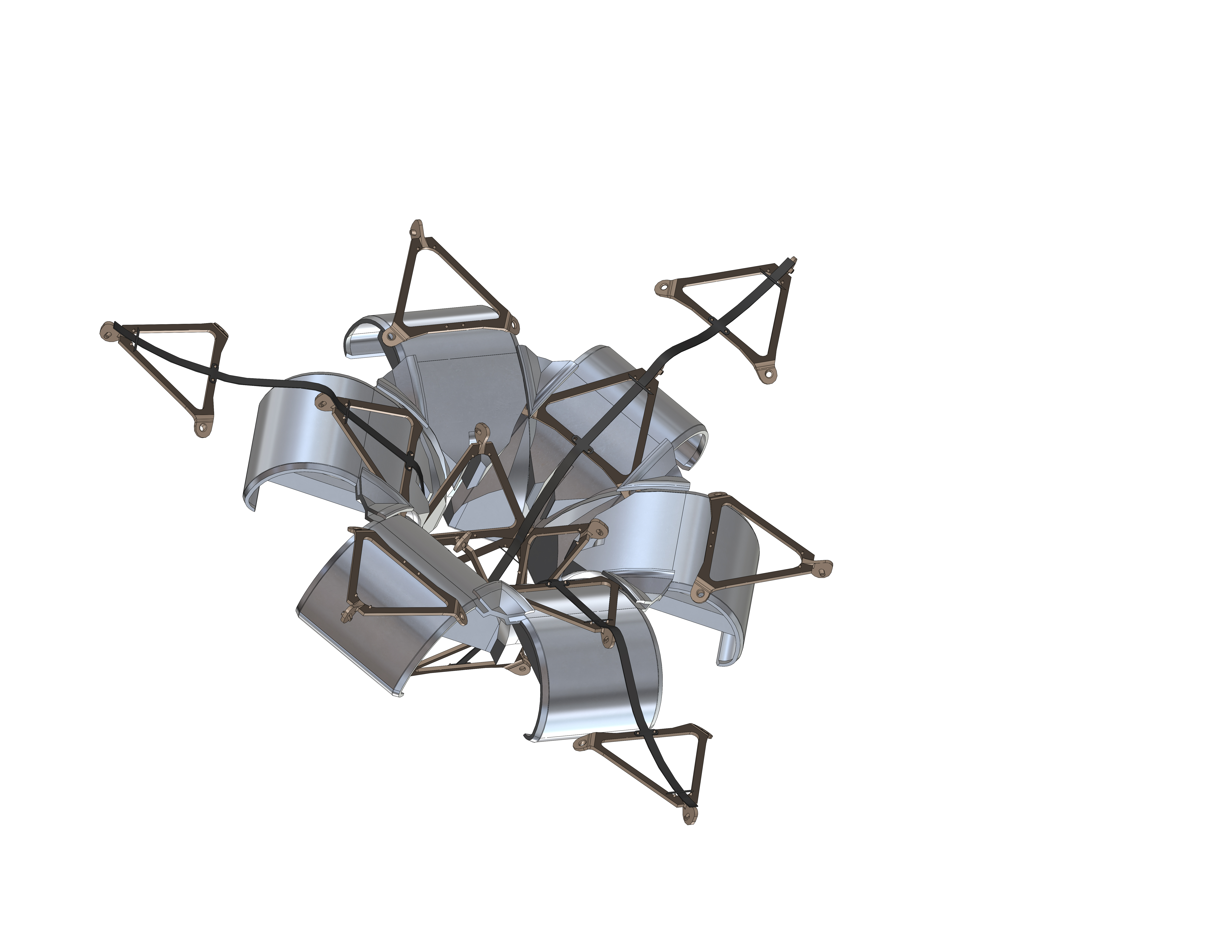
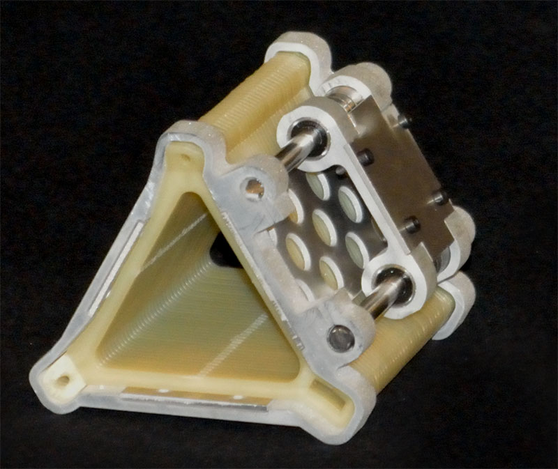
A triangular discrete element assembles into octahedral cells and a face-connected octahedron column motif. The parts balance kinematic alignment features between their interfaces and the assembler itself. A further description of the part geometry is explained in this pdf.


Locomotion, part placement and material handling are the three major design categories. While they are each interdependent they can be separated into singular testable studies. Within each category there exist significant hurdles, such as how to locate onto and fixture to the structure during locomotion. Material handling requires not only moving the primary part into place, fixturing it to its neighboring part but also managing the pin that fixtures pieces into place. Ideally the entire assembly machine could be driven by a single prime-mover and mechanical linkages time each of the motions. This would make the assembler more machine than robot (imagine a well tuned engine or powerful sewing machine).
Locomotion studies are investigating methods of traversing the lattice. Different lattice geometries lend themselves to different locomotion schemes. The octa-turret allows an integration of locomotion with part placement. This animation demonstrates the general motions. The primary nature of the locomotion is a motion away from the structure to clear the previously placed part a lateral motion extending along the axis of the structure and a return to fixturing back to the structure in a new placement. There have been three methods explored so far:
Material handling and part placement require holding parts in orientation, moving them to their final location and fixturing them, accurately. The higher density packing the better for space and reload efficiency. Eventually the parts will assume some geometry that helps their handling. The magazine is different than most magazine driven devices. In common machines such as staplers, nail guns, machine guns the magazine stores the parts orthogonal to the direction of operation. This makes passive loading relatively simple. However, due to the shape of the part and the desire to flat-pack the parts tend to want to be oriented in the same direction as their operation. This requires mechanisms to hold back the stored parts while manipulating the in-action component. Also, ideally the material handling is passive and does not require additional power to operate in-situ.
Experiments are underway with spring-loaded, cam, lifter mechanisms. A belt driven system was also tested. Timing on of all three belts proves to be fairly difficult, and important.
 |
 |
 |
The currently most promising direction is to implement the leap-frog with an additional linear motion at the foot. This allows the single plane motion of the rotation of the leap-frog actuator while providing transverse clearance for the lateral manuever, as shown in the above animation. Maximum packing density and a removeable magazine is possible. This requires a separate actuator for the linear motion and there are space restrictions for the drive motor which must be somewhat substantial to lift a fully loaded magazine (depending on its final load capacity).
Preliminary shopbot
CBA, Dr. Matt Carney 2015
